How to map a plug-in's parameters to control surfaces.
Contents
Introduction
Control Surfaces Overview
A tactile, external hardware control surface can be used to control different aspects of an application such as Pro Tools or Media Composer. Purpose-built control surfaces for DAW manipulation are often preferred over other input devices such as a mouse or keyboard due to the control surface's superior accessibility, tactile feel, ergonomics, and user feedback.
Avid provides several different control surface products designed to accommodate a wide variety of user needs and workflows. Most Avid control surfaces implement EUCON (Extended User Control), a high-speed open control protocol featuring high-resolution, responsive control over almost all software functions. Some other control surfaces, such as the C|24, implement a dedicated control protocol for direct integration with Pro Tools. Finally, Pro Tools includes support for Mackie's HUI protocol and can interface with third-party control surfaces that implement this protocol.
Page Tables Overview
When a control surface is attached to a DAW system running AAX plug-ins the surface can be used to manipulate plug-ins' parameters. Plug-ins define the mapping between their parameters and control surface encoders using page tables.
Abstractly, a page table is a static mapping of a plug-in's controls to the interface of the control surface. Since a plug-in may have many more controls than the control surface can accommodate at a given time, the controls may be split across several "pages" that the user can freely switch between.
More concretely, a set of page tables is simply a set of single dimensional arrays. Each slot of the array corresponds to a particular rotary encoder or push-button of the control surface. By inserting control indices into the elements of the array, a plug-in's controls are mapped to particular tangible controls of the CS. Page tables are stored as XML data created by the PeTE (Page Table Editor) application available on the developer.digidesign.com website.
The following sections describe the various interfaces that the supported control surfaces provide for modifying plug-in parameters. Later, the specifics of implementation of page tables is described.
Avid Control Surfaces
EUCON
Avid S6
The Avid S6 is a modular control surface solution for the most demanding audio mixing and production environments. Built on the same proven technology that is core to the industry-leading ICON and System 5 product families, the Avid S6 enables mixers to quickly turn around complex projects while swiftly handling last-minute changes. With its unparalleled ability to simultaneously control multiple Pro Tools and other EUCON-enabled DAWs over simple Ethernet, S6 also speeds workflows and enables network collaboration on a single integrated platform.
The main touch screen display on the Avid S6 can be configured to show graphs representing a plug-in's frequency or dynamics response curves. To support this feature, a plug-in must implement
AAX_IEffectParameters::GetCurveData() for the applicable
AAX_ECurveType selector.
Avid S3
The Avid S3L System is a modular live sound solution including an HDX-powered processing engine, scalable remote I/O, and a EUCON-enabled control surface.
At the heart of the Avid S3L system lies the E3 engine. The E3 runs Windows Embedded and a version of VENUE software that can load AAX DSP plug-ins onto a built-in HDX platform. Accompanying the E3 engine is the S3 control surface and one or more Stage 16 remote I/O boxes. The S3 is a compact 16-fader control surface with built-in I/O and 32 touch-sensitive rotary encoders, each with a high-resolution OLED display.
On the S3 control surface, the top-right eight encoder/OLED pairs may be dedicated to any plug-in instance. In addition, the S3 includes support for dedicated EQ and dynamics plug-ins: a user can select a particular plug-in as his EQ or dynamics processor and use the surface's EQ, Compressor/Limiter, and Expander/Gate selectors to bring up the plug-in in a separate group of eight encoders. This mode uses the plug-in's D-Control Center Section EQ or Dynamics page tables when mapping plug-in controls. In order to be selectable as the system's EQ or dynamics processor a plug-in must meet the criteria for an ICON center-section plug-in.
Avid Artist Series: MC Control v2
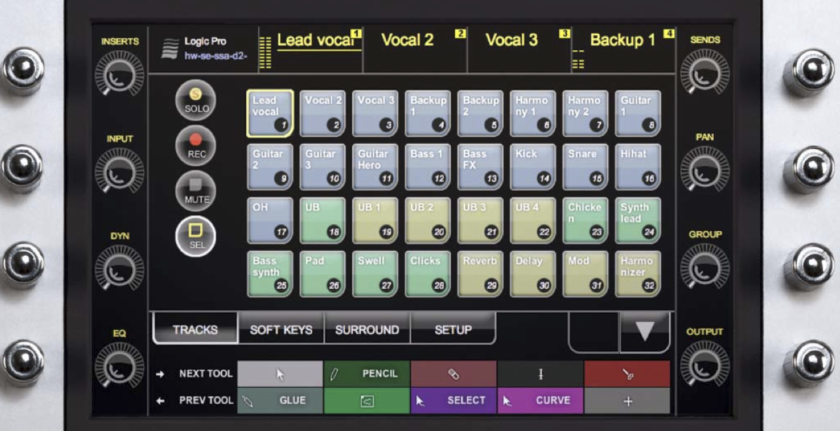
The MC Control v2 can run as either a standalone device or connected to additional units to form a larger system for your favored DAW. See Figure 1
Figure 1: EUCON Artist Series: MC Control v2
The plug-in editing section for the MC Control v2 consists of 8 touch and velocity sensitive rotary encoders, and 8 touch screen switches. The rotary knobs are physically laid out as two groups of 4, vertically aligned and positioned next to the customizable LED-backlit touch-screen interface, with their corresponding touch screen switches right next to them. The alpha-numeric scribble strip and plug-in editing displays are 8 characters wide. The knobs and switches can be assigned using the Av81 page table.
Mapping of plug-in parameters to the surface's various controllers can also be done through use of the ProControl or D-Control page tables, giving the MC Control the ability to emulate various plug-in editing sections(D-Control's Center Section EQ/Dynamics Sections and Channel Strip ) or as a dedicated plug-in editing section (ProControl). Consequently, if using the ProControl page table, plug-in developers will have access to 16 controls, rotary encoders numbered top to bottom, left to right, as 0 through 7, and touch screen switches numbered top to bottom, left to right, as 8 through 15.
Avid Artist Series: MC Mix
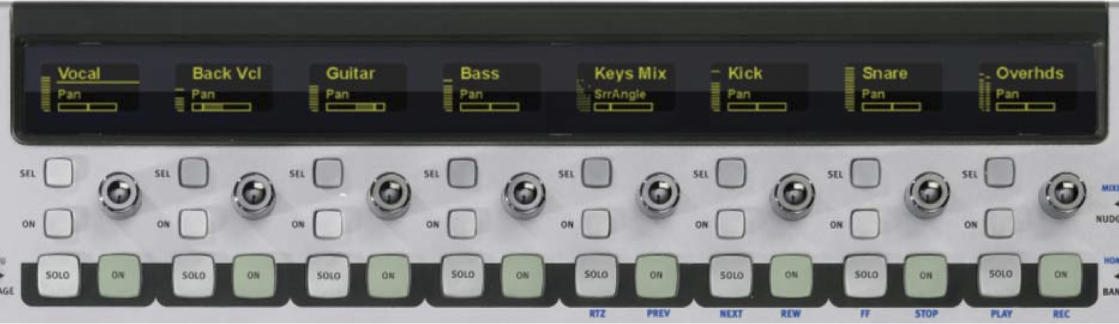
The MC Mix can run as either a standalone device or connected to additional units to form a larger system for audio mixing applications. See Figure 2.
Figure 2: EUCON Artist Series: MC Mix
The plug-in editing section for the MC Mix consists of 8 touch and velocity sensitive rotary encoders, and 8 switches. The rotary knobs are physically laid out horizontally along the top of the control surface as a goup of 8, located right below the display screen, with the switches located directly below the encoders (the "ON" buttons). The alpha-numeric scribble strip and plug-in editing display are 8 characters wide. The MC Mix is mapped using the Av18 page table, with the recommendation that the most important parameter is listed first. Like the MC Control v2, mapping of plug-in parameters to the surface's various controllers can be done through use of the ProControl and/or D-Control page tables. This allows the MC Mix to emulate the various plug-in editing sections that pertain to the D-Control, as well as the ProControl's dedicated plug-in section. Both rotary encoders and switches are numbered right to left, as 0 through 7, and 8 through 15 respectively.
Avid Pro Series: System 5
The System 5 Avid series consists of digital audio mixing systems that can be configured with hundreds of channels. These systems are used specifically for audio post production and music applications. Channels have a 4 band EQ, dynamics, two filters, and consist of 8 rotary knobs and a touch-sensitive motorized fader.
The plug-in editing section consists of 8 knob/switch pairs. This section can take it's mapping from the Av81 page table, with the recommendation that the most important parameter is last (closer to the operator). Like the Artist Series of EUCON controllers, mapping of plug-in parameters can also be accomplished through use of either ProControl or D-Control page tables. When using these page tables, the plug-in editing section is numbered top to bottom, 0 through 7, and 8 through 15, respectively.
The System 5 can also be put into a mode where a single plug-in is mapped across 4 rows of rotary knobs across an entire 8-fader bank. This mode uses the Av48 page table.
Avid Pro Series: MC Pro
The MC Pro is a workstation control surface that is geared towards professional post production. As the professional version of Avid's Artist Series MC Control, it delivers precise and fast control of your editing applications.
The plug-in editing section consists of 8 pairs of touch-sensitive rotary knobs and switches. The rotary knobs are equipped with LED display rings that are available for control of EQ, Dynamics or any type of control your plug-in may need. As with the MC Control v2, plug-in parameters can be mapped with the EUCON Av81 page table or by the ProControl or D-Control page tables described below. The 8 knobs are placed as two vertical groups of 4, laid out on the left half of the control surface, and are numbered top to bottom, left to right.
Avid C|24 and ICON
C|24
C|24 is a hardware control surface allowing great flexibility and power to Pro Tools systems. The alphanumeric scribble strip and plug-in editing displays allow 4 characters each for the plug-in name and a control's name. Three characters are allowed for the control's value.
The plug-in editing section consists of 24 horizontally aligned data encoders and 24 switches lined up under the encoders. (Figure 3 above shows only 12 so that more detail can be displayed.) The C|24 encoders and switches are set up as pairs. In any given control pair, either the encoder OR the switch is used, depending on how the control has been defined in the plug-in. A control defined as a discrete control with two possible values is automatically assigned to the switch of an encoder/switch pair. A control with three or more possible values is automatically assigned to the encoder. If the control is set to the encoder in a pair, the switch in that pair will be disabled. Therefore, whether the plug-in has all switches, all encoders, or a mix, there are 24 controls available per page on the C|24.
ICON: D-Control ES
D-Control is a modular hardware control surface that adds high-quality tactile mixing and editing capability to Pro Tools systems. D-Control is a high-end mixing system that includes a center section and one or more fader packs. A fader pack consists of 16 channel strips, displaying track and plug-in information. Further general information about D-Control and how it works is available from the "BuckleyBriefing.pdf" on the developer website.
D-Control has the potential of displaying plug-in controls in four different sections: Channel Strip, Custom Fader, Center Section EQ, and Center Section Dynamics. The Dynamics section actually makes use of two different page table types, while the other three each have one page table type. In all sections, scribble strips are 6-characters wide and do not support the Digidesign Extended character set (i.e. special characters).
-
Channel Strip
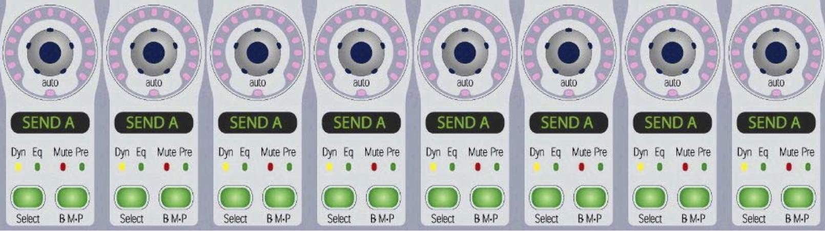
Plug-ins' controls are displayed in the channel strip section of the D-Control. Each channel strip consists of 6 vertically aligned encoder/switch pairs. This gives a total of 12 controls per page, where the encoders (from top to bottom) are numbers 1-6, and the switches (from top to bottom) are numbered 7-12. Like ProControl, the lower numbered encoder is paired with the lower numbered switch. In the diagram to the right, the button labeled "B-M-P" will control the switch.
There are a couple of special considerations when making D-Control Channel Strip page tables. First, keep in mind that the strips are at the top half of the control surface. Therefore, it will be more convenient for the user if you place the most frequently used controls at the bottom rather than at the top. Second, when a control is present in the switch of an encoder / switch pair, the "Pre" light will be lit as an indication to the user of the switch's presence. However, the name of the control placed on the switch will not appear in the scribble strip, unless the user presses the Sw Info button. The value of the switch will appear when the switch is pressed, but the name does not appear. Therefore, it is not recommended that you place a switch next to an empty encoder. It is recommended that you either place a switch next to an encoder that makes sense (like a Gain encoder next to a Phase switch) or place the switch control in both the switch and encoder so that the user will see the name of the control. These are merely guidelines, and not hard and fast rules.
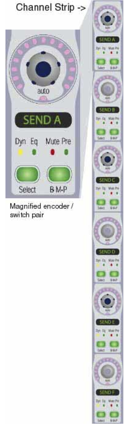
Figure 4: D-Control: Channel Strip
-
Custom Fader
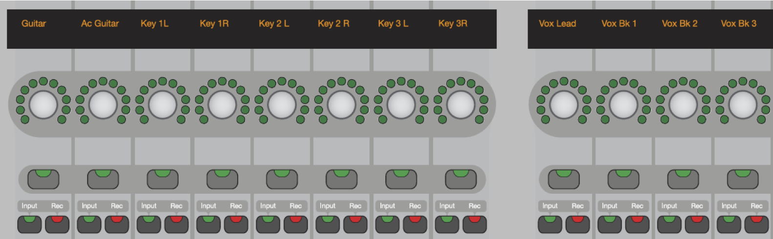
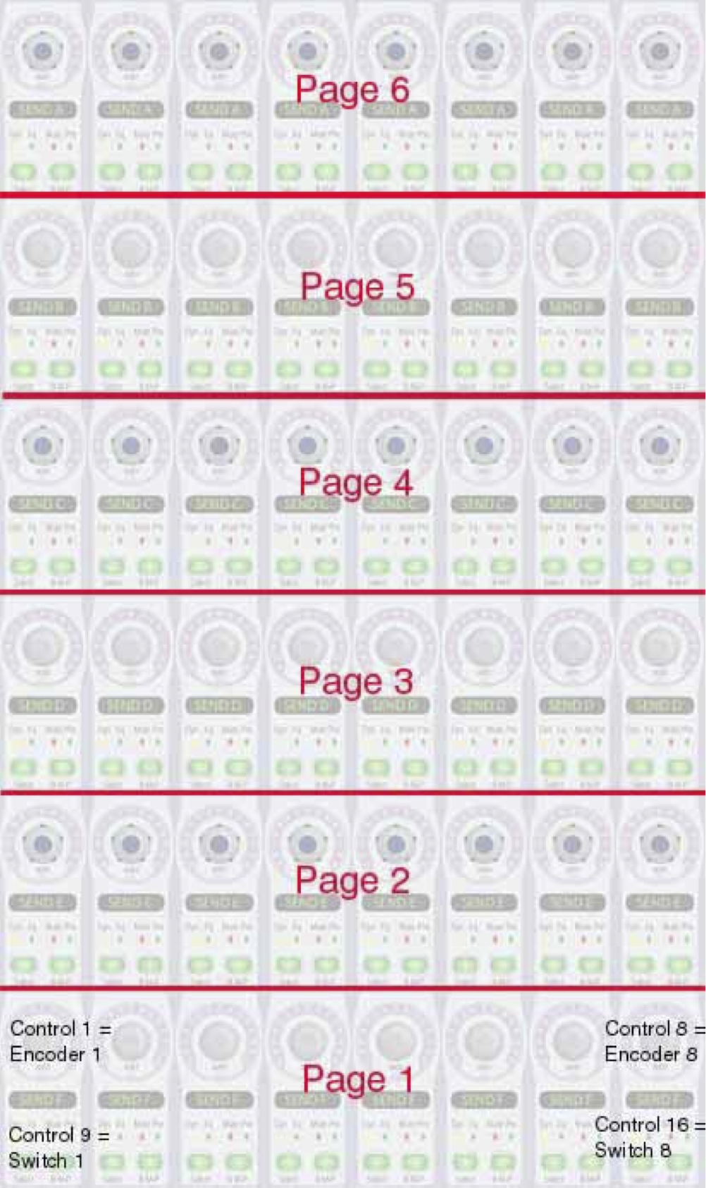
D-Control can be placed in a special mode called Custom Fader to allow more controls of a plug-in to be displayed at once. D-Control takes the currently selected plug-in and displays its controls across 8 of the 16 channel strips such that the plug-in's first control is in the lower left control, its eighth is in the lower right. If there is more than one page of controls, D-Control displays additional pages, up to six, in the rows above the first. If the user has more than one fader pack, the Custom Faders can spread to more sets of faders.
Figure 5: D-Control: Custom Fader
Figure 6: D-Control: Custom Fader Page Layout
To support this mode, a plug-in must include a page table with 16 controls (8 encoder/switch pairs) per page. See the diagram to see how the layout of several Custom Fader page table pages works.
Since the one page layout is similar to the ProControl layout (16 controls per page with 8 encoders and 8 switches), D-Control will use your plug-in's ProControl page tables as a default. If you are not happy with how your plug-ins controls appear in this manner, you can override this by creating a Custom Fader page table.
-
Center Section EQ and Dynamics Sections
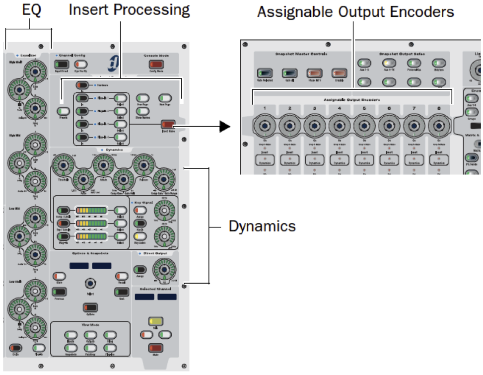
D-Control's center section contains two dedicated areas for EQ and Dynamics plug-ins. Only plug-ins falling into these categories (EQ, Compressors, Limiters, Expanders, and Gates) should implement page tables for these sections. If your plug-in does not fall into these categories, you can skip these page table types. The remainder of the descriptions of these types can be found below in the Center Section Page Tables section.
ICON: D-Command ES
D-Command ES is a more compact yet expandable console than the D-Control. Coming standard with 8 physical faders/channel strips (two encoders per strip), it is expandable to 40 faders/channels.
The plug-in editing section for the D-Command follows closely to that of the D-Control, with two encoders per channel strip. It provides dedicated Dynamics and EQ sections for plug-ins that support Dynamics and EQ plug-in mapping, as well as the ability to display plug-ins in a Custom Fader section as described in the D-Control section. All sections provide scribble strips that 6 alpha numeric characters wide.
VENUE
VENUE is a revolutionary line of digital live sound systems that deliver amazing sound quality, reliability, flexibility, and ease-of-use. These live sound systems come equipped with plug-in editing sections, and work together to deliver studio-grade sound and powerful performance.
D-Show
The VENUE D-Show System is based around the VENUE D-Show console and employs a VENUE FOH Rack and Stage Rack processing and I/O system. This system offers the greatest amount of I/O and console expandability of all the VENUE systems available.
Figure 7: D-Show: Plug-In Controls
The plug-in editing section consists of 8 horizontally aligned rotary encoders, located on the right half of the center of the console. Additionally, D-Show also has dedicated EQ and Dynamics sections available for use on both input and output channels. To map plug-in controls to the encoders use ProControl and D-Control (Center Section) page tables, described in the sections below.
Profile
The VENUE Profile System is based around the VENUE Profile console. It offers great I/O expandability in a smaller footprint than the D-Show.
The plug-in editing section consists of 8 horizontally aligned rotary encoders, located on the right half of the center of the console. Additionally, D-Show also has dedicated EQ and Dynamics sections available for use on both input and output channels. As with D-Show, use the ProControl and D-Control page tables to map plug-in controls to the available encoders.
Plug-In Page Table Guidelines
This section is intended as a guide in setting up defined 'pages' using some general rules. However, due to the sheer number of variables, it is simply not possible to account for all scenarios. But by following these suggestions, an AAX plug-in developer should find these guidelines useful in setting up their own plug-in pages. Moreover, it is hoped that a consistent and somewhat standard mapping topology will be realized across the broad range of plug-ins and control surfaces.
Here, we are primarily concerned with the number of controls on a control surface (CS) available for plug-in editing; and secondarily with the layout of controls provided for plug-ins. Accordingly, we need a method of mapping a plug-in's control parameters to a CS, and we need to take into account the varying numbers of controls available on a CS. Using 'page tables', from a software point of view, a plugin's control parameters can be mapped to a CS. Each page of the page table describes which of the plugin's parameters will be accessible from the CS's controls that are used for plug-in editing. Multiple pages are needed in the case where a CS has fewer controls available than the actual number of controls on a plug-in. We begin by stating guidelines that should be followed when mapping a plug-in's control parameters to a CS. At the end of this chapter, you will find the technical details of creating page tables for your plug-in.
The following guidelines are for simple, generic control surfaces. More advanced CSs, such as the MackieHUI and ProControl, have some guidelines of their own which are listed after these.
General Guidelines
Map a plug-in's controls from left-top to right-bottom sequentially onto each page.
Follow the layout of the plug-in GUI as closely as possible, allowing the controls to sequentially map to the Control Surface in the order specified above. In so doing, the CS controls will match the plug-in GUI; in the sense that by counting the location of a given control on the PI GUI, one should be able to grasp the corresponding slider or pot on the CS.
Note that Master Bypass, located in the plug-in's floating inserts window, should nearly always be placed as the first control on the first page. The only time this guideline might not be followed is if the plug-in has a particularly favorable layout for the control surface, and where this placement of Master Bypass would disrupt it. Also, on some control surfaces a dedicated bypass is already provided, in which case theMaster Bypass should not be mapped into the page table.
Related control parameters should be grouped together on the same page.
Controls that are often 'adjusted' with other similar or related controls should be mapped to the same page. This enhances the users ability to tweak related parameters and alleviates unnecessary paging.
Related control parameters should not be split across pages.
This follows directly from the bullet above. If some closely related controls cannot all fit on the same page, it is better to leave some blanks (i.e., unused pots, sliders, or switches) and move onto the next page where they can be adjusted together.
As a hypothetical example, let's say a control surface has 5 sliders, and we are mapping an EQ PI with 6 parameters - a low, mid, and high frequency band which has gain for each band. It would be best to map them to the CS as follows on page 1, from left to right on the CS: low freq, low gain, mid freq, mid gain, blank. Then map the remaining two parameters onto page 2: high freq, high gain, blank, blank, blank.
Equivalent left and right stereo parameters should remain on the same page.
Since adjusting the left or right parameter of a stereo PI has considerable impact on the sound field, it is important that equivalent left and right stereo controls remain on the same page. Contrast this to placing the left parameters on one page, and the right parameters on another which is not desirable. This rule also changes according to the controller's layout. As an example, the CS-10 has 6 pots for PI editing arranged in a matrix of 3 rows x 2 columns. From left to right, the pots in row 1 are numbered 1 and 4. In row 2 the pots are numbered 2 and 5. Finally, the pots in row3 are numbered 3 and 6. A layout for L/R controls should be mapped param1L = control 1, param1R = control 4, and so on.
Repeat control parameters on pages where it makes sense to do so.
In some situations, it is desirable to have access to the same control on many pages. For example, this might mean having an output and/or input gain control available on each page of an EQ PI - since EQs change the overall gain. This is especially desirable if there would otherwise be blanks (i.e., unused pots, sliders, or switches).
Avid Center Section Page Tables
These page tables are currently used by the D-Control/D-Command (ICON), D-Show (VENUE), and EUCON-enabled consoles. The examples in this section will mostly refer to D-Control. Venue developers, please see the D-Show specific documentation for further details. The plug-in library API,
GetParameterValueInfo(), works hand in hand with these page table types. You may optionally implement this method for enhanced support of several buttons and status LED's on these sections. There are three Center Section page table types, defined in FicHWController.h:
const OSType cDigiEQPageTable = 'DgEQ ';
const OSType cDigiCompLimPageTable = 'DgCP ';
const OSType cDigiExpGatePageTable = 'DgGT ';
Listing 1: Center Section page table types
The first type is for EQ plug-ins (and supports the D-Control EQ section). The second type is for compressor and limiter plug-ins (and supports the D-Control Dynamics section). The third type is for expander and gate plug-ins (and supports the D-Control Dynamics section). Dynamics plug-ins that include both types of processing should support both DgCP and DgGT page tables.
While future control surfaces will use these same page tables, the physical layout of the controls on these other surfaces may be different than on D-Control. However, our goal is that your plug-ins will be able to automatically work on these new surfaces without any additional work.
It is important to note that these three page table types are different from all other page table types in a fundamental way:
Each slot in the page table is pre-defined for a specific type of control. Therefore, your plug-in must conform to this pre-defined layout.
The purpose of the Center Section is to give the user a standard interface for EQ and Dynamics plug-ins - no matter what particular plug-in they are using. It allows the user to quickly access the most common controls in their favorite EQ or Dynamics plug-ins. This is different from all other page table types because the only restriction on other page table types is that - for types that have dedicated discrete controls - you cannot place continuous controls in a dedicated switch. However, the user will also know that if there are controls they would like to access that are missing from the Center Section, they can access them through one of the other layouts available on the control surface.
You'll notice looking at the pictures of these sections in D-Control (below) that the only scribble strips are in the center of the section. Unlike the Channel Strip section, there is not a scribble strip to label each control. The control's purpose is physically printed on the control surface. That is why it is imperative that your plug-in conform to the pre-defined layout. You can find the definition of these page table types in FicHWController.h and in the PeTE editor. Because of the strict definitions of the layouts, it may mean that 1) not all of the controls for your plug-in can fit in these sections, and that 2) there may be controls your plug-in does not have and therefore are blank in this view. For example, let's say your plug-in is a 10-band EQ that does not have individual Q controls on any of the bands. Such a plug-in will be forced to leave off some of its bands, even though all Q controls specific to the bands on the page table are empty. That is fine as there will be another way for the user to display the plug-in on the control surface that will include all of the controls. For example, on D-Control, a user can also view an EQ or Dynamics plug-in in both the Channel Strip and Custom Fader modes which will display all controls. The important point is this:
Do not place a control in a Center Section page tables that does not fit its prescribed definition.
If you do, the control's function will be mislabeled and will cause confusion for the user. The main purpose of the Center Section is to give the user a standard experience when using EQ and Dynamics plug-ins. Continuing that train of thought, you should only implement one page for these Center Section layouts. This is different from the other page table types, where it is expected to implement as many pages as necessary to give access to all controls in the plug-in. In the case of the Center Section layouts, you should only define one page, except in the case when the plug-in has separate controls for each channel (Left, Right, Center, etc.).
More than one page in Center Section layouts is allowed only if the plug-in has separate controls for each channel.
For example, if your EQ plug-in allows the user to change the EQ differently for the left and right channels, then you would implement two pages for the DgEQ page table. You'll notice in the pictures below for the EQ and Dynamics sections of D-Control, there are buttons labeled for channel selections (L, LC, C, RC, R, etc.). The control surface will automatically map the pages to the buttons, according to the standard order for surround channels. For example, in a stereo EQ, Left controls should be in the first page, and Right controls in the second. D-Control will automatically map page 1 to the L button and page 2 to the R button.
We cannot emphasize strongly enough that trying to fill in all of your controls into these layouts, whether it is by creating extra pages, or by filling in empty slots, will only serve to confuse the user. You must adhere strictly to the guidelines given for these sections.
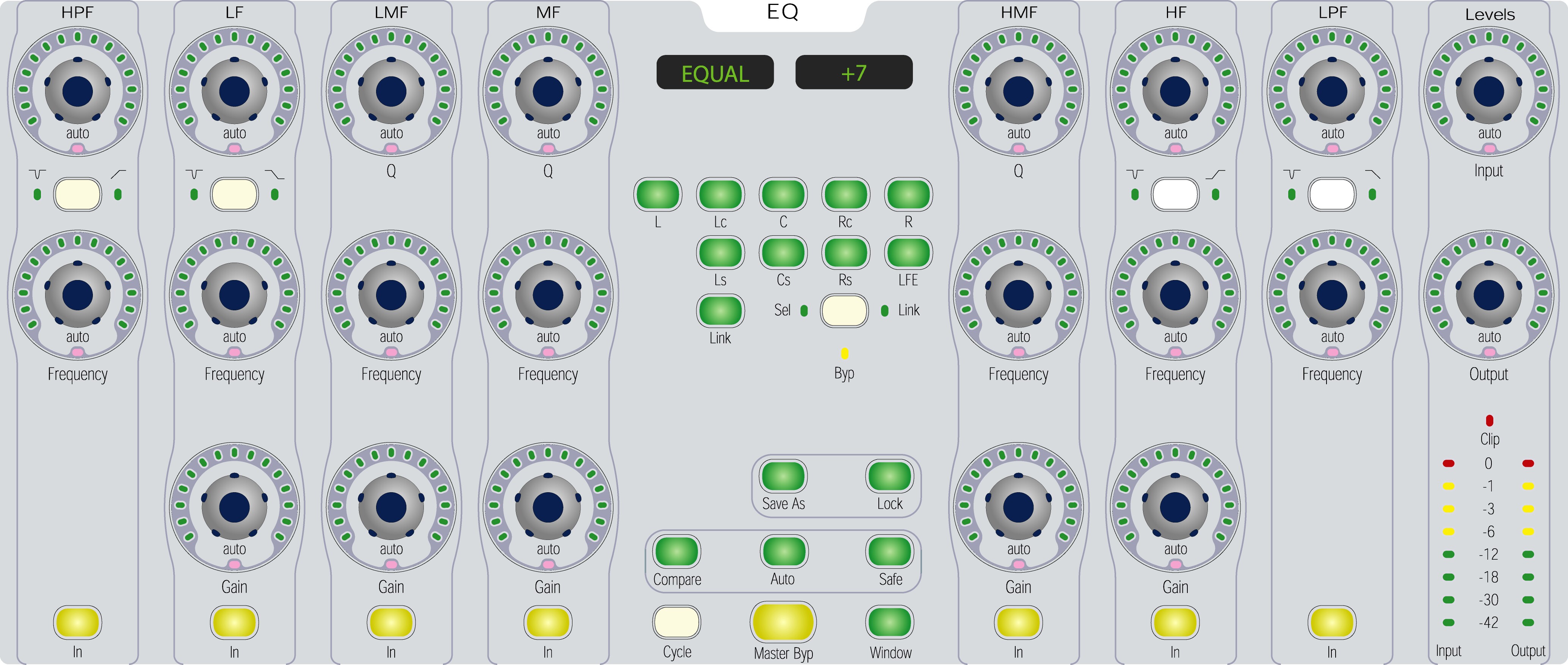
Take a look at D-Control's EQ section more closely in Figure 8.
Figure 8: D-Control EQ Center Section.
It supports a maximum of seven bands of EQ, each a vertical column of controls and labeled from left to right as follows:
-
HPF (High-Pass Filter, nominally a high-pass filter or low frequency notch filter)
-
LF (Low Frequency, nominally a parametric EQ or low frequency shelf filter)
-
LMF (Low-Mid Frequency, nominally a parametric EQ)
-
MF (Mid Frequency, nominally a parametric EQ)
-
HMF (High-Mid Frequency, nominally a parametric EQ)
-
HF (High Frequency, nominally a parametric EQ or high frequency shelf filter)
-
LPF (Low-Pass Filter, nominally a low-pass filter or high frequency notch filter)
Each of these bands has a Q/Slope control, Frequency control, and an In Circuit/ Out of Circuit button. Five of the bands have an additional Gain control. Four of the bands have an additional EQ type selector switch, each surrounded by a pair of EQ type LED's. Input and Output Level controls are also available, as is a multi-channel Link button in the middle section.
- Note
- If an EQ plug-in implements a band that does not have an In/Out Circuit control or a Type control, but wants the related LED's to light properly, please see the discussion of the
GetParameterValueInfo() API below.
The topmost rotary encoders in the HPF, LF, HF, and LPF bands are not labeled but they are indeed Q / Slope controls. The EQ type selector switches located between the Q/Slope and Frequency knobs control the type of filter on that band. Thus they define the behavior of all controls in that band (and not just the unlabeled Q/Slope control).
Starting with Pro Tools 6.9 and the 6.9 Plug-in SDK, controls have been added to the EQ page table type. Previously, the page table only defined one slot in each band for Q and Slope. Since the page tables only allow one control to be defined in any given slot, it was determined that this design was insufficient to allow for plug-ins that may require separate controls for Q and Slope in the same band. Therefore, the page table has been updated with one additional slot per band (called
xxx_Q_Or_Slope_Alt) to handle this case. In order to use this feature, a plug-in must respond to the
AAX_ePageTable_UseAlternateControl selector in the
GetParameterValueInfo() method. When the band type is changed, the control surface will call into the plug-in with this selector to determine if the control in the "Alt" position should be used. Please see the discussion of the
GetParameterValueInfo() below.
The EQ page table indices map to the dedicated EQ Center Section hardware encoders as follows:
-
Equalization 'DgEQ'
-
High Pass - In Circuit switch
-
High Pass - Type switch
-
High Pass - Frequency
-
High Pass - Q/Slope
-
Low Filter - In Circuit switch
-
Low Filter - Type switch
-
Low Filter - Gain
-
Low Filter - Frequency
-
Low Filter - Q/Slope
-
Low-Mid Filter - In Circuit switch
-
Low-Mid Filter - Type switch
-
Low-Mid Filter - Gain
-
Low-Mid Filter - Frequency
-
Low-Mid Filter - Q/Slope
-
Mid Filter - In Circuit switch
-
Mid Filter - Type switch
-
Mid Filter - Gain
-
Mid Filter - Frequency
-
Mid Filter - Q/Slope
-
High-Mid Filter - In Circuit switch
-
High-Mid Filter - Type switch
-
High-Mid Filter - Gain
-
High-Mid Filter - Frequency
-
High-Mid Filter - Q/Slope
-
High Filter - In Circuit switch
-
High Filter - Type switch
-
High Filter - Gain
-
High Filter - Frequency
-
High Filter - Q/Slope
-
Low Pass - In Circuit switch
-
Low Pass - Type switch
-
Low Pass - Frequency
-
Low Pass - Q/Slope
-
Input Gain
-
Output Gain
-
Multi-channel Link switch
-
High Pass - Q/Slope alternate parameter
-
Low Filter - Q/Slope alternate parameter
-
Low-Mid Filter - Q/Slope alternate parameter
-
Mid Filter - Q/Slope alternate parameter
-
High-Mid Filter - Q/Slope alternate parameter
-
High Filter - Q/Slope alternate parameter
-
Low Pass - Q/Slope alternate parameter
If your plug-in supports fewer than seven simultaneous bands of EQ, you have some options for where to place them. We recommend the following placement guidelines so users have consistency with various EQ plug-ins.
-
If you only have one band of EQ, please use the LF band.
-
If you have one to four fully parametric bands, please use LF, LMF, HMF, and HF (starting from left to right). (Skip the MF band.)
-
If you have up to two shelving filters and two parametric bands, please use LF (LF shelf), LMF (para), HMF (para), and HF (HF shelf). (Skip the MF band.)
Note that this layout includes a few additional controls not in D-Control's EQ section to accommodate future Digidesign control surfaces. These extra controls are:
eDigi_EQPageTable_LMF_Type
eDigi_EQPageTable_MF_Type
eDigi_EQPageTable_HMF_Type
Listing 2: Center Section page table types
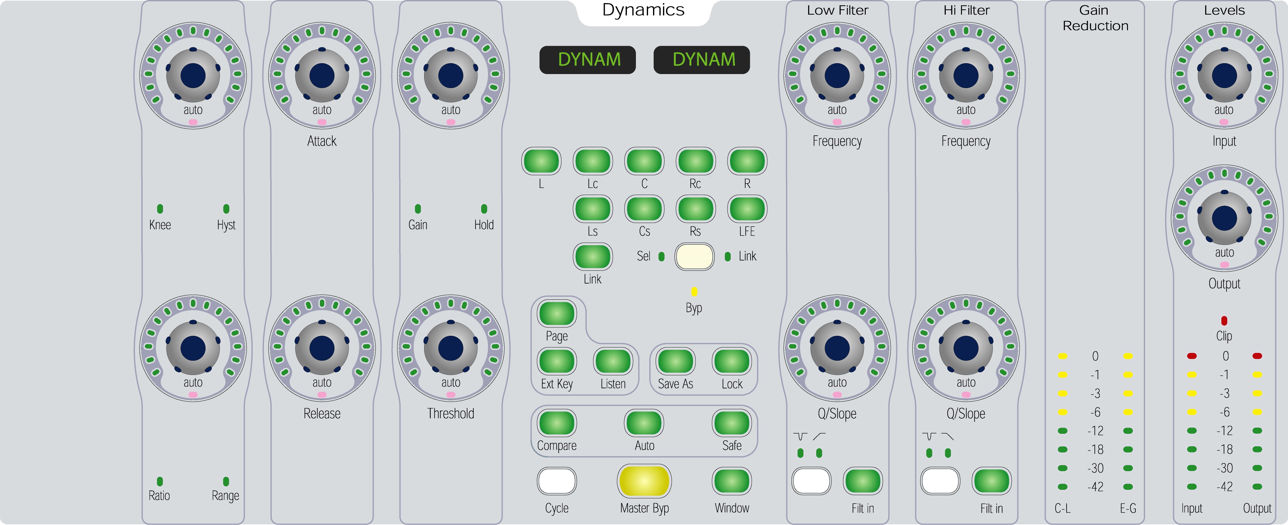
Now we'll look at D-Control's Dynamics section in Figure ?. Keep in mind that the D-Control's Dynamics section displays page tables for both the Compressor/Limiter page table type and the Expander/Gate type. Therefore, the function of certain rotaries and switches differs depending on which page table type has been loaded. In these cases, there is a LED to indicate the current function of a rotary or switch.
Figure 9: D-Control Dynamics Center Section.
Several rotary encoders have alternate uses while others are always dedicated to one function. The two page tables' indices map to the dedicated Dynamics Center Section hardware encoders as follows:
The compressor/limiter page table, DgCP, supports all the controls above except Range, Hysteresis, and Hold. (As you create the page table in PeTE, this is clear.).
The expander/gate page table, DgGT, supports all the controls above except Knee and Makeup Gain. It does support both Ratio and Range. The user presses the Page button to select between them.A plug-in can support both DgCP and DgGT page tables. Again, the user presses the Page button to select between them. If a plug-in supports both of these page tables and the DgGT page table includes support for both Ratio and Range controls, pressing the Page button will switch between all available controls as follows:
DgCP -> DgGT with Ratio -> DgGT with Range (and all other controls unchanged)-> DgCP -> ...
Implementing Page Tables
Page table XML specification
This section includes a rough specification for plug-in page table XML. Whenever possible, we encourage developers to use the PeTE tool to generate plug-in page tables rather than writing or editing the page table XML by hand.
The page table XML format contains three main tags:
PageTableLayouts tag
This section provides a static mapping of control elements to page table layouts. Multiple layouts may be provided in this section, e.g. in cases where different control sets are used by different plug-in Types.
Each layout includes a complete set of page table descriptions. There are multiple kinds of page tables, each of which may have multiple pages. At minimum, each layout must include a PageTable with type='pgTL' and pgsz='1'. This is the default page table, and the order of the control elements that it describes must match the order in which the corresponding parameters are added to the plug-in itself.
Here is an excerpt from the PageTableLayouts section in Avid's Eleven plug-in page tables demonstrating non-EUCON PageTable elements:
<PageTableLayouts>
<Plugin manID='Digi' prodID='ElvF' plugID='ELFr'>
<Desc>Eleven Free 1 -&gt; 1 by Digidesign, Inc.</Desc>
<Layout>PageTable Free</Layout>
</Plugin><!--manID='Digi' prodID='ElvF' plugID='ELFr'-->
<Plugin manID='Digi' prodID='Elvn' plugID='ELVr'>
<Desc>Eleven 1 -&gt; 1 by Digidesign, Inc.</Desc>
<Layout>PageTable 1</Layout>
</Plugin><!--manID='Digi' prodID='Elvn' plugID='ELVr'-->
<!-- ... -->
<PTLayout name='PageTable 1'>
<PageTable type='BkCS' pgsz='12'>
<Page num='1'>
<ID>Mic Type</ID>
<ID>Cab Type</ID>
<ID>Amp Type</ID>
<ID>Master</ID>
<ID>Gain 2</ID>
<ID>Gain 1</ID>
<ID>Mic Axis</ID>
<ID>Cab Type</ID>
<ID>Amp Type</ID>
<ID> </ID>
<ID> </ID>
<ID>Bright Switch</ID>
</Page><!--num='1'-->
<Page num='2'>
<!-- ... -->
</Page><!--num='2'-->
<Page num='3'>
<!-- ... -->
</Page><!--num='3'-->
</PageTable><!--type='BkCS' pgsz='12'-->
<!-- ... -->
<PageTable type='PgTL' pgsz='1'>
<Page num='1'>
<ID>Master Bypass</ID>
</Page><!--num='1'-->
<Page num='2'>
<ID>Input Gain</ID>
</Page><!--num='2'-->
<Page num='3'>
<ID>Output Gain</ID>
</Page><!--num='3'-->
<Page num='4'>
<ID>Gate Threshold</ID>
</Page><!--num='4'-->
<!-- ... -->
</PageTable><!--type='PgTL' pgsz='1'-->
</PTLayout><!--name='PageTable 1'-->
<PTLayout name='PageTable Free'>
<!-- ... -->
</PTLayout><!--name='PageTable Free'-->
</PageTableLayouts>
The sub-tags for this section are as follows:
-
Plugin element
A high-level description of a single plug-in Type.
The manID, prodID, and plugID attributes must match the corresponding Manufacturer, Product, and Type IDs for each plug-in Type that is described in the XML file. Multiple Plugin elements may be included in a single XML file.
The Plugin element has two sub-elements:
-
The
Desc sub-element provides a brief description of the plug-in Type. This information is used only by PeTE and does not affect operation of the plug-in in Pro Tools.
-
One
Layout sub-element is used to bind the plug-in Type to a particular PTLayout (see below.)
-
PTLayout element
A complete control mapping, including a full set of PageTable descriptions.
-
PageTable sub-element - A single page table mapping, with controls specified across multiple Page elements as in the example above.
PageTable elements have the following attributes:
-
type defines the particular device that will use the PageTable. For a description of each device's size and mapping characteristics see the plug-in SDK manual. type may be one of:
-
PgTL - Generic page tables (any size)
-
PcTL - ProControl, VENUE, and EUCON page table (size 16)
-
MkTL - Makie HUI page table (size 8)
-
HgTL - 002/003 and Command|8 page table (size 8)
-
FrTL - Control 24 and C|24 page table (size 24)
-
BkCS - ICON Channel Strip (size 12)
-
BkSF - ICON Custom Fader (size 16)
-
DgGT - ICON dynamics section (Gate/Expander) (size 20)
-
DgCP - ICON dynamics section (Compressor/Limiter) (size 19)
-
DgEQ - ICON EQ section (size 43)
-
Av81 - EUCON 8x1 section (size 24)
-
Av18 - EUCON 1x8 section (size 24)
-
Av48 - EUCON 4x8 section (size 96)
-
pgsz defines the number of controls per page in the page table. Most page table types require a specific size, as noted above. The generic PgTL page tables may be of any size, and multiple PgTL page tables may be provided. However, each plug-in must provide a PgTL page table of size 1 that includes all of the plug-in's automatable parameters, in the order in which they are added to the plug-in.
EUCON PageTable elements
Plug-ins should implement specific EUCON page tables to take advantage of EUCON-specific features and layouts. By writing EUCON-specific page tables, your plug-in is able to re-define both the in/out button as well as the select button per EUCON control cell (on compatible surfaces).
- Host Compatibility Notes:
- Pro Tools versions prior to Pro Tools 11.1 use plug-ins' ProControl and ICON page tables (Dynamics, EQ, Channel Strip, Custom Fader, etc.) to map plug-in parameters to EUCON-enabled surfaces, so be sure that your plug-ins also implement these page tables correctly so that users with earlier versions of Pro Tools can have the best possible experience when using your plug-ins.
EUCON page tables use modern formatting, making them more intuitive to implement than non-EUCON tables. Here are some example lines from a EUCON page table:
<PageTable type='Av18' pgsz='24' >
<Page num='1'\>
<Cell row='1' col='1' knobID="Knob1" inOutButtonID="Button1A" selectButtonID="Button1B" />
<Cell row='1' col='2' knobID="Knob2" inOutButtonID="Button2A" selectButtonID="Button2B" />
<Cell row='1' col='3' knobID="Knob3" inOutButtonID="Button3A" selectButtonID="Button3B" />
...
</Page\>
...
</PageTable >
The EUCON
PageTable element includes a series of
Cell sub-elements. The attributes of each
Cell sub-element are as follows:
-
row - the cell's row position
-
col - the cell's column position
-
knobID - the parameter ID associated with the knob in question
-
inOutButtonID - the parameter ID associated with the "In" button next to the knob in question. This must be a discrete parameter.
-
selectButtonID - the parameter ID associated with the "Sel" button next to the knob in question. This can be a discrete or continuous parameter. If it is a continuous parameter then pushing "Sel" will toggle the knob associated with the button between the selectButtonID and knobID parameters.
- Note
- All parameter IDs must be defined with a
Ctrl ID tag elsewhere in the page table XML.
Beginning in Pro Tools 11.1, Pro Tools supports the following three EUCON-specific table types:
| Av81 | Av18 | Av48 |
| type='Av81' | type='Av18' | type='Av48' |
| 8 rows | 1 row | 4 rows |
| 1 column | 8 columns | 8 columns |
| pgsz='24' (3 elements per cell) | pgsz='24' (3 elements per cell) | pgsz='96' (3 elements per cell) |
| Used for horizontal strips on the System 5 as well as MC Control and MC Pro | Used by Artist Series MC Mix | Used when editing a plug-in across an 8-fader bank of knobs on a supported surface such as System 5 |
| Most important parameters should be placed last (closest to user) | Most important controls should be placed first | Layout should be similar to plug-in GUI where possible |
ControlNamesVariation tag
This section includes information about the names of each control in the plug-in. Here is an excerpt from our Eleven plug-in page tables which demonstrates the basic format of this section:
<Ctrl ID='Amp Bypass'>
<name typ='PgTL' sz='1'>AB</name>
<name typ='PgTL' sz='4'>AByp</name>
<name typ='PgTL' sz='5'>A Byp</name>
<name typ='PgTL' sz='6'>AmpByp</name>
<name typ='PgTL' sz='7'>Amp Byp</name>
</Ctrl><!--ID='Amp Bypass'-->
<Ctrl ID='Amp Type'>
<name typ='PgTL' sz='1'>AT</name>
<name typ='PgTL' sz='3'>Amp </name>
<name typ='PgTL' sz='5'>AmpTp</name>
<name typ='PgTL' sz='6'>AmpTyp</name>
<name typ='PgTL' sz='7'>Amp Typ</name>
</Ctrl><!--ID='Amp Type'-->
<Ctrl ID='Bright Switch'>
<name typ='PgTL' sz='1'>Brt </name>
<name typ='PgTL' sz='6'>Bright</name>
</Ctrl><!--ID='Bright Switch'-->
The sub-tags used are as follows:
Ctrl ID element - The long name of the control that is being identified.
This ID should be identical to the name parameter provided when constructing the control object and should match the IDs used for the control both in the <PageTableLayouts> layouts and in the Editor tag's DiscCtrls sub-tag (see below).
name element - The desired abbreviated name of the control for display on control surface UIs, which may have limited display space available.
The typ parameter allows you to choose which page table type the given abbreviation will be specific to. For example, a name provided with typ='HgTL' would only appear on Command|8, 002, and 003 hardware. As with all other tags, the name associated with typ PgTL (the generic page table identifier) will be used if no other name is given for the specific page table that is being loaded.
The sz parameter defines the size of the control surface display for which the given name is appropriate. The control surface will use the name associated with the largest size that will fit on its display.
To reduce the number of names that must be specified, abbreviated names can be given that are longer than their specified size. These names will be truncated when necessary. For example, a control surface that could accommodate two characters on its display would use the size-1 name for the "Bright Switch" control above, since 1 is the largest number less than or equal to 2 from the provided set of name sizes (in this case, 1 and 6.) The size-1 name, 'Brt ', has four characters in it. Therefore, it would be truncated down to 'Br' to fit onto the control surface's display.
Editor tag
The last of the three main sections in an XML plug-in page table is the Editor section. This section is used by the PeTE editor and you should not need to modify its contents. However, if you are encountering problems modifying your plug-in in PeTE then you may wish to verify that all plug-ins and controls are properly identified within the PluginList and DiscCtrls sub-tabs, respectively. Here is the Editor section from the Eleven page table XML:
<Editor vers='1.3.7.1'>
<PluginList>
<TDM>
<PluginID manID='Digi' prodID='Elvn' plugID='ELVt'>
<MenuStr>TDM: Eleven, 1 in X 1 out</MenuStr>
</PluginID><!--manID='Digi' prodID='Elvn' plugID='ELVt'-->
</TDM>
<RTAS>
<PluginID manID='Digi' prodID='Elvn' plugID='ELVr'>
<MenuStr>RTAS: Eleven, 1 in X 1 out</MenuStr>
</PluginID><!--manID='Digi' prodID='Elvn' plugID='ELVr'-->
<PluginID manID='Digi' prodID='ElvF' plugID='ELFr'>
<MenuStr>RTAS: Eleven Free, 1 in X 1 out</MenuStr>
</PluginID><!--manID='Digi' prodID='ElvF' plugID='ELFr'-->
</RTAS>
</PluginList>
<DiscCtrls>
<CtrlID>Amp Bypass</CtrlID>
<CtrlID>Amp Type</CtrlID>
<CtrlID>Bright Switch</CtrlID>
<CtrlID>Cab Bypass</CtrlID>
<CtrlID>Cab Type</CtrlID>
<CtrlID>Master Bypass</CtrlID>
<CtrlID>Mic Axis</CtrlID>
<CtrlID>Mic Type</CtrlID>
</DiscCtrls>
</Editor><!--vers='1.3.7.1'-->
Creating page tables in PeTE
Page tables can be created and edited using the Page Table Editor (PeTE) application available on the Developer website. PeTE generates an XML file that can then be used in both Windows and Macintosh plug-in projects. The XML is compiled into the plug-in as a resource using a call to
AAX_IEffectDescriptor::AddResourceInfo().
const AAX_CTypeID cDemoDist_TypeID_MonoNative =
'DmRT ';
const AAX_CTypeID cDemoDist_TypeID_StereoNative =
'DsRT ';
Listing 3: DemoDist Plug-In ID's
.
.
.
<Plugin manID ='AVID ' prodID ='DmDE ' plugID ='DmRT '>
<Desc > DemoDist 1 -&gt; 1 by Avid Technology , Inc .</ Desc >
<Layout > PageTable 1</ Layout >
</ Plugin ><!-- manID ='AVID ' prodID ='DmDE ' plugID ='DmRT '-->
<Plugin manID ='AVID ' prodID ='DmDE ' plugID ='DsRT '>
<Desc > DemoDist 2 -&gt; 2 by Avid Technology , Inc .</ Desc >
<Layout > PageTable 1</ Layout >
</ Plugin ><!-- manID ='AVID ' prodID ='DmDE ' plugID ='DsRT '-->
<Plugin manID ='AVID ' prodID ='DmDE ' plugID ='DDT1 '>
<Desc > DemoDist 1 -&gt; 1 by Avid Technology , Inc .</ Desc >
<Layout > PageTable 1</ Layout >
</ Plugin ><!-- manID ='AVID ' prodID ='DmDE ' plugID ='DDT1 '-->
<Plugin manID ='AVID ' prodID ='DmDE ' plugID ='DDT2 '>
<Desc > DemoDist 2 -&gt; 2 by Avid Technology , Inc .</ Desc >
<Layout > PageTable 1</ Layout >
</ Plugin ><!-- manID ='AVID ' prodID ='DmDE ' plugID ='DDT2 '-->
.
.
.
Listing 4: DemoDist XML
- Note
- PeTE will automatically import legacy page tables from existing plug-ins
At a minimum, generic page tables of sizes of 5, 6, 8, and 16 should be provided, along with page tables for D-Control (all applicable types), Procontrol, C|24, Digi002, Command|8, and Mackie HUI.
Though not required, it is also possible to set up other page sizes. This may be advantageous if your plugin lends itself well to a particular layout scheme. In this case, if a newer CS appears on the market, your plug-in will be ready to support it. If your plug-in does not specify a page table explicitly for the newer CS, it will still support it; but the mapping will be based on a Generic page table, first of the same size as the new CS, and if that is not found, then of page size of one. Note that the ordering of controls in dialog boxes, e.g. Plug-in Automation dialog, is determined from the one-control-per-page layout. Therefore, for these reasons, it is important that a Generic page table of size one is defined! There are ten different resource IDs for the ten currently supported page table types. Table 1 outlines these IDs.
Table 1: Resource ID's for supported page table types
| Page Table Type | ID |
| Genric | PgTL |
| D-Control |
|
| D-Command |
|
| Channel Strip | BkCS |
| D-Control |
|
| D-Command |
|
| Custom Fader | BkSF |
| Center Section EQ | DgEQ |
| Center Section Comp/Lim | DgCP |
| Center Section Exp/Gate | DgGT |
| ProControl/VENUE/EUCON | PcTL |
| Control 24/C|24 | HgTL |
| Digi002/003/Command|8 | HgTL |
| HUI | MkTL |
After compiling a plug-in project, a resource will be created containing the XML data. If after editing page tables in PeTE, you want to quickly test your changes, you can do the following:
-
After editing your page tables in PeTE, save the file with a higher version number than the last saved file
-
Copy the XML file created by PeTE to the Plug-ins folder and drop it next to your plug-in
-
Change the name of the file to PluginFilename.xml. PluginFilename must match exactly the plug-ins filename. For example, if your plug-in's file name is RectiFi.aaxplugin, the XML file must be called RectiFi.xml
-
Launch Pro Tools. AAE will find the file, and as long as its version number is higher than the XML compiled into the plug-in, it will load the file's page tables. Although page tables and control surface support do require a lot of attention to detail, plug-ins that are control surface aware are essential to paving the way for the next generation of powerful digital audio tools. And we believe that this has far-reaching benefits for everyone, including plug-in developers!
Verifying Page Table Layouts: The Hidden Pop-Up Menu
You can verify the page tables created in your plug-in in Pro Tools with a "hidden" developer debug Page Tables popup menu. To verify the page tables, first include the YourPageTables.r file in your project and compile the plug-in. Then, after launching Pro Tools, instantiate the plug-in, hold down the Commandkey (Ctrl-key in Windows) and mouse-click the Automation button in the plug-in window to display the menu.
-
Category
The Category menu item has a submenu listing the names of possible categories. Any category that the plug-in belongs to will have a check mark next to it. In addition, appended to the name of the category is an indication of whether that category can be bypassed, and if so, the control number (#) and control name of the associated bypass control. Also appended is the number of the first page on which a control associated with the category can be found. This page number is based on whatever the current page table type is selected in the "TableType" menu item. For example: Delay (can bypass, control #9, Master Bypass) (first page #1)
-
Table Type
Sets the type of control surface page table.
-
Page Size
Sets the number of controls per page. The identifier "custom" is shown next to page sizes that have been specifically implemented (which at minimum, should appear next to page sizes of 5, 6, 8, and16! ). The identifier "default" is shown next to page sizes that do not have specific support in your page table file. Note that the Mackie and ProControl table type will automatically set this to 8 and 16, respectively.
-
Control Name Length
Sets the number of characters to be displayed in the control's name (shown in the Page menu below). The identifier "expected length" appears next to lengths that should be specifically addressed (3, 4, 5, 6, 7, 8, and 31). If you use the XML page table system, the names can be specified in the PeTE application. Otherwise, the function GetControlNameOfLength() is responsible for providing names with these lengths.
-
Control Value Length
Sets the number of characters to be displayed in the control's value (shown in the Page menu below). The identifier "expected length" appears next to lengths that should be specifically addressed (4, 5, 6, 7, 8, and 31; also, 3 is used for ProControl switch states). The plug-in Library call GetValueString() is responsible for providing values with these lengths.
-
Highlighted Page
Highlights the selected page in the plug-in window in Pro Tools.
-
Highlight Color
Sets the highlight color. The highlight color can be: red, green, blue or yellow. Note that at minimum, plug-in's should support these four colors of highlighting!
-
Page X
The actual page table layouts are shown here. The following information can be seen in this menu item.
-
The control's name, as returned from the XML page tables. If the table type is Mackie, then the length will be 4 (unless overridden by changing the "Control Name Length" menu item). If the table type is ProControl, the length will be 3 (again, unless overridden, but usually there is no point in doing so). Also, with ProControl set as the table type, the special ProControl symbols will appear here if they are part of the name (however, note that they are small and can be difficult to see). Finally, if the table type is default, the name will be shown with the number of characters as specified in the "Control Name Length" menu item.
-
The control's value is shown next. Both the Mackie and ProControl table types will automatically set the control's value length to 4 and 3, respectively. Otherwise, this can be set with the "Control Value Length" menu item. GetValueString() is responsible for providing this 'value' information.
-
The number of control steps is shown next for continuous and discrete controls. For example, a discrete control will appear as: "(discrete: N steps)", where N is the # of steps of the control.
-
If "(NoL)" is displayed, this simply means that it is a new plug-in, and supports either the XML page tables or the GetParameterNameOfLength() function call. If "(NoL)" does not appear, then the plug-in is older and you should not expect the control names or values to be optimized - since they are created by just truncating the longer values that the older plug-ins return.
-
If "(highlight)" is displayed, this means that the string will be reverse highlighted when displayed on hardware controllers that support it. Not all hardware controllers utilize reverse highlighting.
-
Next, orientation flags for each plug-in control will be displayed. The format is: "(Value: xxx yyy)," where xxx is either "BMin" (kDAE_BottomMinTopMax) or "TMin" (kDAE_TopMinBottomMax); and yyy is either "LMin" (kDAE_LeftMinRightMax) or "RMin" (kDAE_RightMinLeftMax). This text identifies the value of the control's orientation flags, as returned by GetParameterOrientation().
-
Also shown is the radial LED encoder-display mode (as returned by GetControlOrientation()) assigned to each control (this radial LED surrounds each encoder). The possible modes are: "spread" kDAE_RotarySpreadMode, "wrap" kDAE_RotaryWrapMode, "boost" kDAE_RotaryBoostCutMode, or "dot" kDAE_RotarySingleDotMode, along with either "RMin" kDAE_RotaryRightMinLeftMax, or "LMin" kDAE_RotaryLeftMinRightMax - indicating which side the minimum AAE value is being mapped to.
Control Highlighting Scheme
Note that plug-in controls that are currently controllable on any page of a plug-in will be highlighted in blue when they are the active page on a control surface. Therefore, it is very important to implement the highlighting of controls in your plug-in. Plug-in highlighting is also used with automation. In general, four common colors should be implemented:
-
Red: Write automated
-
Green: Read automated
-
Blue: Accessible on control surface (stays blue if control is also read automated)
-
Yellow: Accessible on control surface and write automated
You can use the "hidden" popup menu above to test that your color schemes are working properly.
Control Numbering Layouts
Most of the advanced control surfaces have both rotary encoders (knobs) and switches. The knobs and switches are handled differently by different surfaces. C|24 has a set of 24 rotary encoders and 24 switches for plug-in editing, and 003 has 8 encoders and 8 switches, all set up in pairs. However, both of these control surfaces automatically assign a control with only two possible values (e.g., "on" or "off") to a switch, while a control with three or more possible values, whether it is discrete or continuous, is automatically assigned to the rotary encoder. Therefore, no distinction is made between control numbers for switches and control numbers for encoders.
The following tables show how the control numbers are arranged for control surfaces which have distinctions between their encoders and switches.
Table 2: D-Control Channel Strip - Numbering Layout
| Encoders | Switches |
| 1 | 7 |
| 2 | 8 |
| 3 | 9 |
| 4 | 10 |
| 5 | 11 |
| 6 | 12 |
Table 3: D-Control/Pro-Control Custom Fader Mode - Numbering Layout
| Encoders | Switches |
| 1 | 9 |
| 2 | 10 |
| 3 | 11 |
| 4 | 12 |
| 5 | 13 |
| 6 | 14 |
| 7 | 15 |
| 8 | 16 |
Alphanumeric Displays
With the advent of the newer advanced control surfaces (CS), plug-ins now have the opportunity to provide information to the user via alphanumeric displays on the CS. Unfortunately, the displays are limited in the number of characters that can be shown. For instance, on the Mackie HUI, nine characters are provided for each plug-in control, allowing only four characters for the control name, and four characters for the control value, and one for a space between them. On ProControl, eight characters are provided for each plug-in control, with three characters allocated to displaying a control name, and four characters for its control value. On C|24 and 003, four characters are provided for the plug-in name, control name, and the control value. For the control value, these four characters include a +/- and/or any necessary unit abbreviations (ex: K, s, dB, etc.). D-Control and Command|8 provide six characters for the plug-in name, control name, and control value.
In order to display meaningful information in these short character strings, plug-ins will have to optimize the strings that they return to AAE. The dispatcher calls MapControlValToString(), which in turn calls GetValueString(), is used to obtain these control value strings. Typically in the past, the requested length argument of both these member functions, i.e., maxChars in MapControlValToString() or maxLength in GetValueString() has been ignored; but, from here on out, they should be carefully examined and used to create an optimum and meaningful string for any requested length.
To prevent the code from becoming unwieldy, as in the case of trying to provide strings for all requested lengths, a minimum number of expected lengths should be specifically addressed. The expected value lengths are: 4, 5, 6, 7, 8, and 31. In addition, ProControl switch states are a maximum length of 3 (i.e., when dealing with the state of a switch for ProControl, provide this information in 3 characters or less). Therefore, whenever possible, a plug-in should return the most meaningful string that will fit in any particular requested length, and at minimum, handle the expected lengths. If a plug-in does not have custom code to handle a particular requested length, it can round the length down to the next smaller expected length and use the code that it has for it. For example, a request of 9 characters should be converted to an expected request of 8 characters.
Please note: Since truncating a long string to fit within the requested length will not provide meaningful results in most cases, plug-ins must specifically provide code for deriving useful strings for the expected lengths at minimum Ñ being as sophisticated as possible, when appropriate.
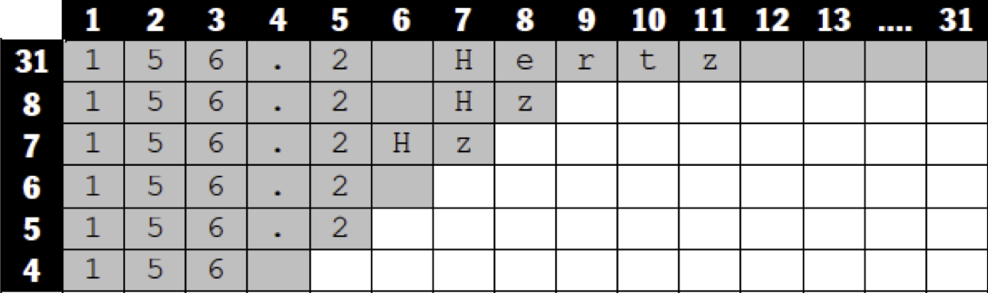
Since the smaller lengths, especially 4 and 5 characters, are usually too short to display a plug-in's true full value including units, some decisions will have to be made about how to suitably shorten them. The following provides some general guidelines.
If needed, and in order of precedence, try to:
-
Remove spaces: 13 Hz becomes 13Hz
-
Use common abbreviations for units: 16 seconds to 16sec, or 16 s, 156 Hertz to 156Hz
-
Drop the units entirely: 1832 Hz to 1832
-
Round the value: 173.3 ms to 173
Here is a table depicting a typical example in more detail. The expected lengths are shown in the left most vertical column.
Figure 10: Alphanumeric Characters
While creating the above strings, the requested length argument passed in (maxChars in MapControlValToString(), and maxLength in GetValueString()) should be strictly adhered to! The string returned should be no greater than the requested number of characters. Furthermore, the developer should assume that the buffer passed into this function is only as large as the requested length. Any intermediate string processing should be done in temporary local buffers and only when you have the final string should you copy back to the buffer that was passed in, making sure you copy no more than the requested number of characters, plus the Null character or Length byte, as appropriate; since in general, MapControlValToString() uses C strings and GetValueString() uses Pascal strings.
Also, in an effort to further help prevent buffer overruns, two new functions have been added to the PI library file SliderConversions.cp: SmartAppendNum() and SmartAppendXNum(), which includes a maximum length argument and should be used in place of FicAppendNum() and FicAppendXNum() from FicBasics.cpp.
Finally, note that ProControl and HUI will sometimes utilize 5 characters to display its value when a sign is involved. For instance, if the number is -100, the negative sign will appear in the space separating the control name from the control value. Pro Tools will take care of this conversion as long as all of the expected lengths are properly provided for. For C|24 and 003, this is not the case - only four characters are allowed, so the +/- must be a part of those four characters.
HUI, ProControl, C|24, and 003 all provide alphanumeric displays for visual feedback, with the primary purpose being plug-in parameter editing. Functions in the plug-in library are provided that allow customized parameter strings to be created for use on the display. Specifically, these functions are: GetControlNameOfLength() and GetValueString(). Fortunately, the details of writing to the display are taken care of by the application. Therefore, the plug-in developer only needs to be concerned with providing meaningful display strings for all plug-in parameters that are controllable. Whether using the XML or legacy page table system, GetControlNameOfLength() should return the long version (31 characters maximum) of the plug-in's control names. Short versions of plug-in control names are stored in the XML file, edited with the PeTE application. If you are also using legacy page tables to support versions of Pro Tools prior to 6.4, the short names should also be coded in the GetControlNameOfLength() function.
AAE clients like Pro Tools call GetControlNameOfLength(), but if AAE finds XML data stored in the plug-in, it gets the information from there rather than calling into the plug-in. GetControlNameOfLength() is responsible for providing the parameter "names" used on the display. As with parameter "value" strings, it is important to carefully create parameter names that are meaningful in the limited space allocated to displaying parameter names. On ProControl, string lengths of three characters will be used for the parameter name strings, where four characters will be used on the HUI, C|24, and 003. D-Control and Command|8 use six characters for control names. In general, lengths of 3, 4, 5, 6, 7, 8, and 31 should be specifically addressed in the PeTE editor or GetControlNameOfLength(). We begin next, by looking at some concrete examples.
ProControl Display
ProControl also provides an alphanumeric display; however, there are some significant differences that need to be addressed. Shown is a generic representation for the ProControl display. Figure 11 shows what users will usually be viewing on ProControl's displays, which are the current Encoder/Value settings. Figure 12 shows the current switch settings when the user toggles to the Switch/State display mode. ProControl will only display one of three views at any given time.
Figure 11: Pro-Control Encoder Display
Figure 12: Pro-Control Switch Display
As with the HUI, meaningful strings will have to be provided in the limited available lengths. ProControl, C|24 or 003 value strings require no special treatment other than what has already been stated above for HUI, since all of these control surfaces display their values in 4 digits/characters, as returned by GetValueString(). The biggest difference between the HUI display and the Digidesign control surfaces displays is that Digidesign CS's can display symbols.
Let's take a moment to explain how the displays of C|24 and 003 work. Both of these surfaces have a four character LED display located above each encoder/switch pair. When in Channel mode, these scribble strips show the plug-in name (if any) on that channel. When that plug-in is selected, the display switches to show the controls for the plug-in. Now each display shows the name of the control. The display automatically switches to the current value of the control when the encoder or switch is moved or pushed.
Appendix A. Get Parameter Value Info
Overview
AAX_Result GetParameterValueInfo ( AAX_CParamID iParameterID, int32_t iSelector, int32_t* oValue)
GetParameterValueInfo() is implemented at the Data Model's
AAX_CEffectParameters level, and will allow the app to query a plug-in for the "meaning" of its parameter values. It was designed as a general purpose mechanism that will find additional uses with new selectors in the future. It is used:
-
to ensure the EQ and Dynamics sections' EQ type selector LEDs light appropriately for a givenband's filter type. We want the appropriate EQ type LED to light for each band's filter type -whether or not your band can switch between filter types.
-
to ensure the state of the EQ section's In buttons matches the values of the associated plug-incontrols. When each band's In button is lit, it must mean that the EQ is active/on/enabled.When it is unlit, it must mean that the EQ is off/disabled/bypassed. (Some plug-ins have EQbypass controls (On = bypass); others have EQ In buttons (On = On). We can derive "meaning" from the control regardless of control value.)
-
similarly, to ensure the state of the Dynamics section's Filt In buttons matches the values of theassociated plug-in controls. When each band's Filt In button is lit, it must mean that the EQ isactive/on/enabled. When it is unlit, it must mean that the EQ is off/disabled/bypassed.
Implementation
Listing 5: Parameter Selector Enums
Listing 6: EQ Band Type Enums
Listing 7: EQ Circuit Polarity Enums
Listing 8: Alternate Control Enum
One point to note, is that an EQ or Dynamics plug-in may have a band of EQ that does not include an EQ type selector control. The band is just always, say, a HPF. There's no control to map to the EQ type selector button in the page table and therefore no obvious control for which you would pass back
AAX_eEQBandType_HighPass in
GetParameterValueInfo(). What is the solution? Well, the other controls on that band (Frequency, Q/Slope, Gain, In) know what type of band they're on. Thus the plug-in should pass back the relevant EEQ_Band_Types enum in
GetParameterValueInfo() for all controls on a given band of EQ. This also applies to key filter bands in your Dynamics plug-ins. In this way, the EQ type selector LEDs in both the EQ and Dynamics sections will always light appropriately.
- Note
- The logic for the In Circuit / Out of Circuit LED is available in Pro Tools 6.7 and higher.
AAX_Result EQIII_7_Parameters::GetParameterValueInfo (
AAX_CParamID iParameterID, int32_t iSelector, int32_t* oValue)
const
{
const AAX_IParameter * parameter = mParameterManager.GetParameterByID( iParameterID );
if ( !parameter )
{
if ( parameter->
Name() == EQIII_HPF_Type )
{
{
}
}
else if ( parameter->
Name() == EQIII_LF_Type )
{
{
}
}
else if (parameter->
Name() == EQIII_HF_Type )
{
{
}
}
else if ( parameter->
Name() == EQIII_LPF_Type )
{
{
}
}
}
{
if ( (parameter->
Name() == EQIII_HPF_Type ) ||
(parameter->
Name() == EQIII_HPF_Q) ||
(parameter->
Name() == EQIII_HPF_Slope) )
{
const AAX_IParameter* typeParam = mParameterManager.GetParameterByID(EQIII_HPF_Type_Ch);
}
else if ( (parameter->
Name() == EQIII_LPF_Type) ||
(parameter->
Name() == EQIII_LPF_Q) ||
(parameter->
Name() == EQIII_LPF_Slope) )
{
const AAX_IParameter* typeParam = mParameterManager.GetParameterByID(EQIII_LPF_Type_Ch);
}
}
};
Listing 9: EQIII GetParameterValueInfo()
As you'll notice, the EQ III plug-in has separate controls for Q and Slope in its HPF and LPF bands, depending on whether the band is set to notch or band pass. When the Band Type control is set to notch, the continuous Q control is used. When the Band Type is set to Hi/Lo Pass, the discrete Slope control is used. In the page table, the HPF / LPF Q controls are set to the ``Q or Slope'' in PeTE, and the HPF / LPF Slope controls are set to the ``Q or Slope Alt''. Then, with the
GetParameterValueInfo() implementation above, the control surface properly swaps the controls when the band type control is changed. In other words, when the function is called with the
AAX_ePageTable_UseAlternateControl selector, if the band type control is set to notch, then
AAX_eUseAlternateControl_No is returned in the result and the control surface puts the Q control at that position. If the band type is set to pass, then
AAX_eUseAlternateControl_Yes is returned and the Slope is placed at that position.


 1.8.5
1.8.5

